← UTIOM
UTIOMv1.4

Think smarter. Stay secure.

Where UTIOM sits next to NIST, SANS and the traditional SOC

How Strategy Enables the UTIOM Lifecycle

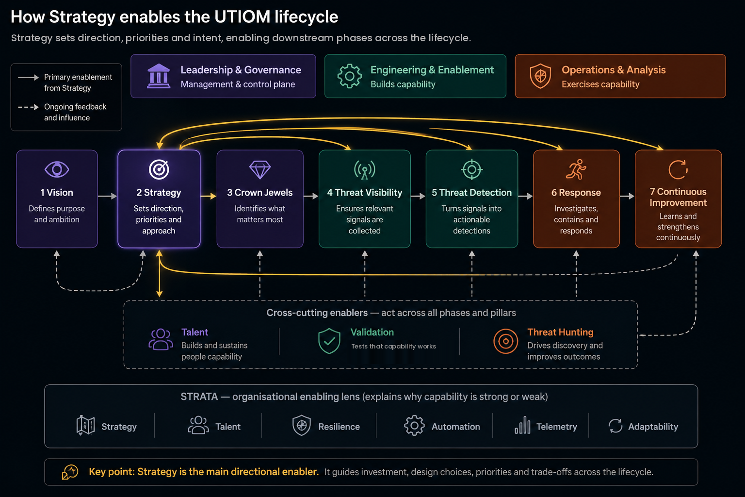
Strategy translates Vision and business context into direction, priorities, investment and design choices that guide Crown Jewels, Threat Visibility, Threat Detection, Response and Continuous Improvement.

UTIOM diagram showing Strategy as the primary directional enabler for downstream lifecycle phases, with the three pillars, cross-cutting enablers and STRATA.
Strategy is the second lifecycle phase, not a fourth cross-cutting enabler: Vision precedes it, and the direction it sets flows to the phases that follow. Click to open the full-size image.

UTIOM Architecture Overview

A canonical view of UTIOM’s three operating pillars, seven lifecycle phases, three cross-cutting enablers, STRATA enabling lens and three assessment tiers. Explained in full at what UTIOM is.

Click to enlarge UTIOM architecture overview Security operations managed as a living product, divided into three operating pillars. Leadership and Governance is the management and control plane holding the Vision, Strategy and Crown Jewels phases. Engineering and Enablement builds capability and holds Threat Visibility and Threat Detection. Operations and Analysis exercises capability and holds Response and Continuous Improvement. Talent, Validation and Threat Hunting are cross-cutting enablers rather than lifecycle phases. STRATA is an organisational enabling lens across all of it. Three assessment tiers provide a system-integrity view of results, where a tier cannot be governed above the tier it rests on. Security Operations, managed as a living product Leadership & Governance Management & control plane Engineering & Enablement Builds capability Operations & Analysis Exercises capability · Analysis & Response LIFECYCLE PHASES 1 Vision 2 Strategy 3 Crown Jewels 4 Threat Visibility 5 Threat Detection 6 Response 7 Continuous Improvement CROSS-CUTTING ENABLERS Talent Validation Threat Hunting Not lifecycle phases. They act across multiple phases and pillars, each with a primary assessment home. ENABLING LENS STRATA — organisational enabling lens Strategy · Talent · Resilience · Automation · Telemetry · Adaptability Explains why capability is strong or weak. Not a maturity score and not an additional assessment domain. ASSESSMENT VIEW Tier 1 — Strategic & Governance Foundation Vision & Governance · People & Operating Model Strategy & Threat Profile · Crown Jewels Tier 2 — Engineering & Operational Capability Threat Visibility · Threat Detection Threat Hunting · Response Tier 3 — Assurance & Evolution Validation & Adversary Emulation Continuous Improvement A tier cannot be governed above the tier it rests on. The tiers do not replace the three pillars, seven lifecycle phases or three cross-cutting enablers. 10 assessed domains · 105 capability indicators · 50 maturity criteria · 70 metrics
UTIOM Diagrams

Eight figures that explain particular aspects of UTIOM, with two appendix tables. The V-Model on the home page stays the canonical model; nothing here replaces it. Colours follow the three pillars used across the site: purple is Leadership & Governance, green is Engineering & Enablement and UTIOM itself, amber is Operations & Analysis, and rust is the alert-driven model and the validation rail.

Leadership & Governance Engineering & Enablement Operations & Analysis Alert-driven model & validation rail
Figure 1

From a siloed security operations centre and reactive incident response to UTIOM

The main transformation: separate SOC functions and a disconnected incident-response workflow become one operating model. On the right, the canonical V-shape with its three pillars, and beneath it the same functions placed on a conceptual distance-to-impact scale — all of them run continuously; what differs is their distance from impact and their intensity.

Click to enlarge SILOED SOC + REACTIVE IR SIEM / vendor content sets the work: whatever fires today alerts Threat IntelHuntingDetection Eng.Monitoring feeds, reportsad hoc huntsrule backlogtriage queue dashed walls: own backlog, own metrics, no shared strategy ticket, escalate Incident Response separate workflow, after the fact negotiates blocking authority during the incident Measures: alert volume, MTTR, tickets closed silent on whether crown jewels are covered post-incident report → filed rarely changes telemetry, rules or the threat model UTIOM · ONE OPERATING MODEL (CANONICAL V-SHAPE) Leadership & Governance Engineering & Enablement Operations & Analysis purpose ↔ metrics proven threat profile ↔ proof attack paths ↔ validated telemetry ↔ proven VisionStrategyCrown JewelsThreat Visibility Detection Engineering Detection QAPurple TeamResponseImprovement design & intent ↓ ↑ validation & operation every design decision on the left has a matching validation on the right; IR is the operating mode, not a separate team CONCEPTUAL DISTANCE TO IMPACT · ALL RUN CONTINUOUSLY Strategic distanceEmerging exposureObservable activityActive threatBusiness impact threat profiling, TIhunting, exposuredetection engineeringmonitoring & analysisdecision & response one capability, one strategy, one risk register — intensity rises as distance to impact shrinks scales from a vCISO with three people to a large SOC · built for cloud, AI-native and critical infrastructure © Reza Adineh · utiom.de
Same functions on both sides. What changes: the trigger (SIEM vs. threat profile and crown jewels), the walls between functions, incident response as a separate workflow vs. the operating mode of the whole model, and whether every design decision has a validation partner.
Figure 2

NIST SP 800-61 and SANS PICERL mapped onto the seven UTIOM phases

Classic NIST and SANS models aggregate preparation into one broad phase. UTIOM decomposes it into Vision, Strategy and threat profiling, and Crown Jewels and attack paths — then explicitly engineers the visibility and detection capabilities required before operational response. Phases 1–3 are preparation and strategic threat orientation, 4–5 engineering and enablement, 6 operational analysis and response, and 7 continuous improvement across the whole lifecycle.

Click to enlarge NIST SP 800-61 r2 · FOUR PHASES SANS PICERL · SIX PHASES UTIOM · SEVEN PHASES, ONE LOOP Preparation readiness assumed, not engineered Detection & Analysis Containment, Eradication & Recovery Post-Incident Preparation readiness assumed, not engineered Identification Contain Eradicate Recover Lessons Learned 1234567 VisionStrategyCrown JewelsThreat VisibilityThreat DetectionResponse ContinuousImprovement purposethreat profileattack paths, treestelemetry eng.rules, QA, hunting analysis · forensics · contain · recover · SOARroot cause → lifecycle PREPARATION & STRATEGIC THREAT ORIENTATION ENGINEERING & ENABLEMENT OPERATIONAL ANALYSIS & RESPONSE LIFECYCLE-WIDE one box · "be ready" detect → analyse/investigate is the 5 → 6 hand-off 4 engineers what preparation assumes phase 7 feeds the whole lifecycle — solid: most frequent update points (2–6) · dashed: strategic findings can change Vision and purpose (1) © Reza Adineh · utiom.de
The crosswalk uses the four-phase lifecycle from SP 800-61 r2 because that is the one practitioners know. Revision 3 (2025) reorganises the same activities under CSF 2.0 functions; the standards-alignment page covers that view. Phase 4 is drawn as a readiness enabler: the standards assume the telemetry exists, UTIOM engineers it.
Figure 3

The operating model in detail

The same three pillars and seven phases as the home page, with what each phase consumes, what it produces, and the outcome it is accountable for. The side panels carry three things the simplified view leaves out: the scope of the priority lens, the guardrails around crown jewels, and the decision-making loop that returns operational reality to leadership.

Click to enlarge THE OPERATING MODELThree pillars, seven phases, and the feedback loops that turn fragmentedsecurity operations into an adaptive control system.LEADERSHIPANDGOVERNANCESet direction,prioritise risk, andallocate resources.ENGINEERINGANDENABLEMENTBuild and evolve thesensing and detectioncapabilities.OPERATIONSANDANALYSISRun the operation,respond at incidenttempo, and capturelearning.1VisionStrategic directionMission and business outcomesRisk appetiteOperating principlesOutcome: Clarity of purposeand north-star alignment2StrategySecOps strategy and targetoperating modelKPIs and capability roadmapGovernance, policy, fundingThreat profiling: adversaries,motives, sectors, likely TTPsOutcome: Prioritised plan andresourced roadmap3Crown jewelsBusiness-critical assets,services, data, identitiesCritical dependencies andtrust boundariesThreat modelling: attack pathsRisk scoring and prioritisationOutcome: Prioritised risks andprotective focus4Threat visibilityTelemetry architectureLog sources and collection pointsTelemetry engineeringSchema, quality, retentionDeTT&CT and TID-CMM alignmentOutcome: Trusted, complete andsearchable telemetry at scale5Threat detectionDetection-as-codeATT&CK, Sigma, analyticsUse cases and hypothesesValidation, tuning, coverageTID-CMM alignmentOutcome: Effective detections withmeasured coverage depth6ResponseTriage and investigationScoping and forensicsContainment, eradication, recoverySOAR, playbooks, coordinationOutcome: Incidents contained andbusiness impact minimised7Continuous improvementLessons learnedMetrics and reportingTuning and backlogUpdated strategy and playbooksTraining and exercisesOutcome: Stronger capabilities andreduced future riskattack paths and threat models decide what must be observableITERATIVE ENGINEERING LOOPDetection requirementsdrive telemetry needsand instrumentationTelemetry validationand coverage insightsinform detectionengineeringPRIORITY & CONSEQUENCE LENSScope includes attack paths, shareddependencies, enabling systems,identities, ordinary endpoints andactivity that can lead to crown-jewelimpact — not just the assetsthemselves.GUARDRAILSPreventive controls, boundaries,exceptions, failures and bypassesaround crown jewels.DECISION-MAKINGFEEDBACK LOOPOperational realityand outcomescontinuously informleadership decisions,strategy, andpriorities.OODA LOOPAt incident tempobetween engineeringand operations.ObserveOrientDecideActTID-CMMmeasures this pillarTIR-CMMmeasures this pillarEach phase consumes and produces knowledge. Outputs of one phase become inputs to the next,creating a continuous, threat-informed incident response lifecycle — not separate silos.KEY LOOPS& FLOWSPrimary flow, phases 1 to 7Strategy to executionIterative engineering loopDetection and telemetry, phases 4 and 5OODA loopEngineering and operations, at incident tempoDecision feedback loopOperational reality informs leadership© Reza Adineh · utiom.de
The flow has ordered dependencies rather than being a waterfall. Vision sets purpose, Strategy turns it into a threat profile and a plan, and Crown Jewels turns that into attack paths and threat models — which is what decides the telemetry Threat Visibility must collect. An arrow from Vision straight to telemetry would claim that collection derives from intent, skipping the work that determines it. The brackets down the left show which pillar each maturity module measures in depth: TID-CMM for Engineering and Enablement, TIR-CMM for Operations and Analysis. Leadership and Governance has no module, which is deliberate. Read the numbered flow first, then the loops: phases 4 and 5 iterate against each other, and Continuous Improvement can change anything upstream of it. This is the operating model a security operations centre runs on. The iterative engineering loop between phases 4 and 5 is the one most often missing in practice: detection requirements should drive telemetry needs, and telemetry validation should feed back into detection engineering. Where that loop is absent, teams collect what is easy and detect whatever the collection happens to allow.
Figure 4

Threat-to-outcome traceability chain

How threats, crown jewels and attack paths generate evidence requirements, and how missing telemetry becomes a Telemetry Engineering requirement before any detection logic is written. This is why TID-CMM is not a framework for writing SIEM rules.

Relevant threats+Crown jewels and attack paths+Engineered telemetry=Defensible detection requirements
Threat intelligence appears twice on purpose: strategically in the threat profile (phase 2) and technically in the evidence requirement (phases 4–5). The two roles have different consumers and different cadences.
© 2026 Reza Adineh · utiom.de
Figure 5

The validation rail across Threat Visibility, Threat Detection and Response

Purple teaming, detection QA and response exercising are not sub-capabilities of phase 5. Together they validate the complete chain from attack path to response, which is why each phase on the left arm of the V has a validation partner on the right.

The rail is drawn in the same rust colour in every figure so it is recognisable as the same mechanism wherever it appears.
© 2026 Reza Adineh · utiom.de
Figure 6

Who pulls the trigger: a conceptual authority progression

Containment authority is designed before the incident, not negotiated during it. This is a conceptual progression of how that authority matures; it is deliberately not numbered and must not be read as the UTIOM maturity scale, which is assessed through its own staged criteria.

Click to enlarge CONCEPTUAL AUTHORITY PROGRESSION · NOT THE UTIOM MATURITY SCALE Nobody defined Escalation chain Designated asset owner Pre-approved playbook Automated, human oversight Autonomous, measured ask, wait for a meeting holds standing authorityto block, right now human executes theplaybook, no approval step SOAR contains on high-confidence detections containment margin vs.breakout time is trackedand rehearsed time to decide: dayshoursminutesminutessecondsseconds, proven the first step where authority is defined before the incident © Reza Adineh · utiom.de
Once the official level descriptors are mapped, each step can be annotated with the UTIOM level at which it becomes a staged criterion; until then the figure stays unnumbered.
Figure 7

UTIOM, TID-CMM and TIR-CMM framework family

UTIOM is the complete operating model. TID-CMM and TIR-CMM add measurement depth on the engineering and response sides and share one end-to-end evidence trail.

TID-CMM's eight domains and TIR-CMM's domains are grouped here into four measurement areas each for readability; the module sites carry the full domain lists and weights.
© 2026 Reza Adineh · utiom.de
Figure 8

The incident response continuum in a security operations centre

The doctrine drawn as a single scale. Threat intelligence, engineering, monitoring, hunting, containment and improvement are not separate functions that hand work to each other. They are incident response at different distances from impact, which is why UTIOM removes the silos rather than coordinating between them.

Click to enlarge UTIOMThere is no “normal SOC work” that is not incident response.Far before impactAt / after impactStrategic, anticipatory IRVisible, high-intensity IR01 — ANTICIPATEKnow whatcould hit usThreat Intelligence + ThreatProfiling = IR before impactVision and strategyCrown jewels and critical assetsMost probable threat actorsTTPs, attack paths and threatmodellingGuardrails, dependencies and likelyabuse pathsRisk-based priorities02 — ENGINEERBuild the abilityto see and actDetection Engineering =IR encoded into logicThreat visibilityTelemetry engineeringDetection-as-codeDeception engineeringPlaybooks and automationTraining and exercisesDetection requirementsdrive telemetry needs.03 — SENSE & SEARCHFind evidenceof the threatMonitoring & Triage = continuousIR sensing. Hunting = IRwithout an alertMonitoring and alertingTriage and correlationThreat analysisHypothesis-led huntingRed teaming and purple teamingvalidate the model, the telemetryand the detections.04 — RESPONDControl therealised threatResponse & Containment =the most visible IRInvestigationForensics and scopingContainmentEradicationRecovery and resilience05 — LEARNMake the nextresponse strongerContinuous Improvement =IR improving future IRMetrics and reportingLessons learnedKnowledge managementOutcome validationCapability improvementEvidence and lessons flow back to threat profiles, crown jewels, models,telemetry, detections, playbooks and training∞One continuous, unified, threat-informed incident response lifecycle — not separate SOC silos.© Reza Adineh · utiom.de
Read left to right as distance from impact, not as a sequence of phases. Everything on this scale runs continuously; what changes is intensity and how visible the work is. The dashed rail underneath carries evidence and lessons back to the profiles, models and detections that produced them, which is what makes it a lifecycle rather than a pipeline.
Appendix · Figure A1

Process view: inputs, outputs and decisions per phase (BPMN-style)

A second view of the same canonical model, redrawn from the original input-flow sketch with the corrections applied. Swimlanes are the three pillars; rounded blocks are the seven phases; documents are the inputs and outputs each block consumes or produces; the diamond is the telemetry decision; dashed message flows are inputs that can arrive from outside the SOC. Nothing here changes the V — it explains how work moves through it.

Click to enlarge LEADERSHIP & GOVERNANCE ENGINEERING & ENABLEMENT OPERATIONS & ANALYSIS 1 · Vision2 · Strategy3 · Crown Jewels purpose, metricsthreat profilingthreat modelling Business purpose,risk appetitewhat must not fail Threat profileadversaries, motives, TTPsstrategic TI Crown-jewel mapattack paths / trees,profile mapped to paths inoutout MESSAGE FLOWS · MAY BE EXTERNAL Technical TIDeception signalsRed-team results which behaviours, artefacts and channels must be observable Required adversary evidenceper node and choke point 4 · Threat Visibility evidence requirements out ? trusted telemetry exists? yes Assure itcoverage, health, parsing no ⊞ Telemetry Engineering (sub-process) enable → collect → transport → parse → normalise → enrich → validate → maintain Inputs: 2 + 3 + 4profile · paths · assured telemetry in 5 · Threat Detection versioned rules, lifecycle,baselines, hunting Versioned detectionsbaselines, test resultshandoff to 6 alert + handoff Incident record, decision time,root causeauthority: designated owner or playbook 6 · Response analyse · decide · containrecover · SOAR 7 · ContinuousImprovement root cause → backlog Prioritised change backlogfor phases 1–6 7 feeds the whole lifecycle — most frequent update points 2–6; strategic findings reach Vision (1) VALIDATION RAIL 4→5→6 · PURPLE TEAMING · QA · EXERCISING © Reza Adineh · utiom.de
Notation is BPMN-flavoured rather than strict BPMN: solid arrows are sequence flow, dotted arrows are data associations (in/out), dashed arrows are message flows from sources that may sit outside the SOC, the diamond is an exclusive gateway, and the ⊞ block is a collapsed sub-process whose steps are the Telemetry Engineering pipeline from Figure 3. Only assured telemetry enters phase 5, on either branch.
Appendix · Figure A2

Per-phase inputs, outputs and validation partner

The same information as A1 in tabular form, for the page where the V-shape is explained. Each row is one block of the process view; the last column is the phase's partner on the right arm of the V.

Rows 4–6 are the span of the validation rail; rows 1–3 are proved indirectly through the same emulations and through Improvement.
© 2026 Reza Adineh · utiom.de

All diagrams © 2026 Reza Adineh · Creative Commons BY-SA 4.0

This page is a summary. The full treatment is in the book: Design and Validation: the V-Model →

Join the UTIOM community. Discuss, contribute evidence and share implementation experience. About the community →